
ARG21 Shutdown Box
Tyler Bisk
Introduction
The function of the GLV_SB is to safely turn off the car when a variety of conditions are met while the car is driving. If a fault is detected somewhere within the car, the shutdown circuit will no longer be continuous. This will cut power to the Accumulator Isolation Relays (AIRs), which will cause them to open. This board is necessary because it ensures that if there is some sort of failure when driving, the car is immediately turned off which minimizes damage to the driver, the crew, or the car itself.
The function of the CHARGE_SB is to handle shutting down the charger if a problem arises while charging. Unlike the GLV_SB, this board is not inside the car, but rather inside the charger. Like the GLV_SB, the board is essential because it allows us to charge the accumulator. If a fault is detected, the board shuts down the charger.
There are many rules regarding car safety and shutdown circuitry that must be complied with in order to race in competition. In summary, my board must detect isolation failure, temperatures and voltages outside an allowable range, and simultaneous braking and acceleration inputs. If one of these faults are detected, an indicator light must illuminate while immediately cutting power to and from the accumulator.
It is my responsibility to make sure that my board exceeds what is specified by the rules in order to be confident that we will get to competition with a rules compliant car. There are four pages of rules pertaining to the GLV Shutdown Box. You can read about them here if you’d like (pages 95-98).
Research
There are three parameters that must be analyzed in order to build the Charging Shutdown Box and five for the Grounded Low Voltage Shutdown Box. Each of these parameters are input signals to the shutdown boxes which indicate the status of other systems. If any of these signals indicate a fault or error that meet the criteria in the rules listed above, the corresponding latching circuit opens open and disables the tractive system (GLV_SB) or the charger (CHARGE_SB). Below is a list of signals that will be monitored, with the type of fault it outputs.
GLV_SB Fault Signals
- Multipurpose Enable
- Open Drain [1]
- Discharge Enable
- Open Drain [1]
- Accumulator Current
- Analog [2]
- Brake Pressure
- Analog
- IMD Fault
- Active Low [3]
CHARGE_SB Fault Signals
- Multipurpose Enable
- Open Drain [1]
- Charge Safety
- Open Drain [1]
- IMD Fault
- Active Low [3]
In order to find these values, one must:
Step 1: Analyze and study the rules for conditions in which a shutdown is required (e.g. Voltage values outside the allowable range)
Step 2: Determine what component is responsible for monitoring this condition (e.g. BMS)
Step 3: Refer to the manual of said component to find what signal is used for the fault in question (e.g. Discharge Enable)
Step 4: Further investigate as to what the expected behavior is of that signal (e.g. Open Drain)
Step 5: Adjust latching circuit to open on fault (discussed in Section 4)
History of the Design
There is a very short history of the GLV Shutdown Box. The GLV_SB was first designed in 2019 by Nicole Lin and Jon Gao [4]. Nicole and Jon’s design first was just a BSPD, but they realized that one board could handle all of BSPD, IMD, and AMS faults. Once they integrated those features, there were three separate latching circuits on the board on their rev2. The idea behind their design is that in normal operation, the tractive system in is shorted with the tractive system out [4]. When there is a fault, the circuit opens which shuts down the car. As of when Cornell was sent home for COVID, their most recent brought up design failed rules. Nicole revised this design but did not lay it out or order a new board.
Last semester, I renamed the Shutdown Box to GLV_SB to be distinguishable from the Charging Shutdown Box that I was soon to develop. I noticed a few errors in the design that was passed down to me from Nicole and Jon. Namely, the signal used to check for BMS fault was incorrect. Two signals would be required to check for a BMS fault, not just one. Additionally, these signals are not active high like initially suspected but rather open drain, something that the original design did not account for and would fail tests if used. There were no large changes with the latching design. This is since their design was thoroughly researched and tested by analyzing what other teams had come up with [4].
The changes in the schematic were significant enough between Nicole and Jon’s rev4 and my rev1 + Nicole’s rules fix over the summer to completely redesign the board and lay it out from scratch. The connector has been changed from last year as well; we are now using AMPSEAL Board-to-Wire connectors instead of last year’s Board-to-Board strategy, which is an improvement because the boards can be physically placed where they best fit inside the car instead of being connected to each other. Now, they take up less volume because there is no wasted space in between boards.
We were forced to go home before Thanksgiving, so only one revision of my board was completely manufactured and tested last fall. The majority of improvements made to the board was done in 2021, which will be discussed extensively further in the report.
I am the first person to design a Charge Shutdown Box. The motivation behind this board was that the GLV Shutdown Box could not be accurately used for charging since the signals are fewer and slightly different than when driving. Constraints for the charge shutdown box were mostly set by rules and the Brusa charger we are using this year.
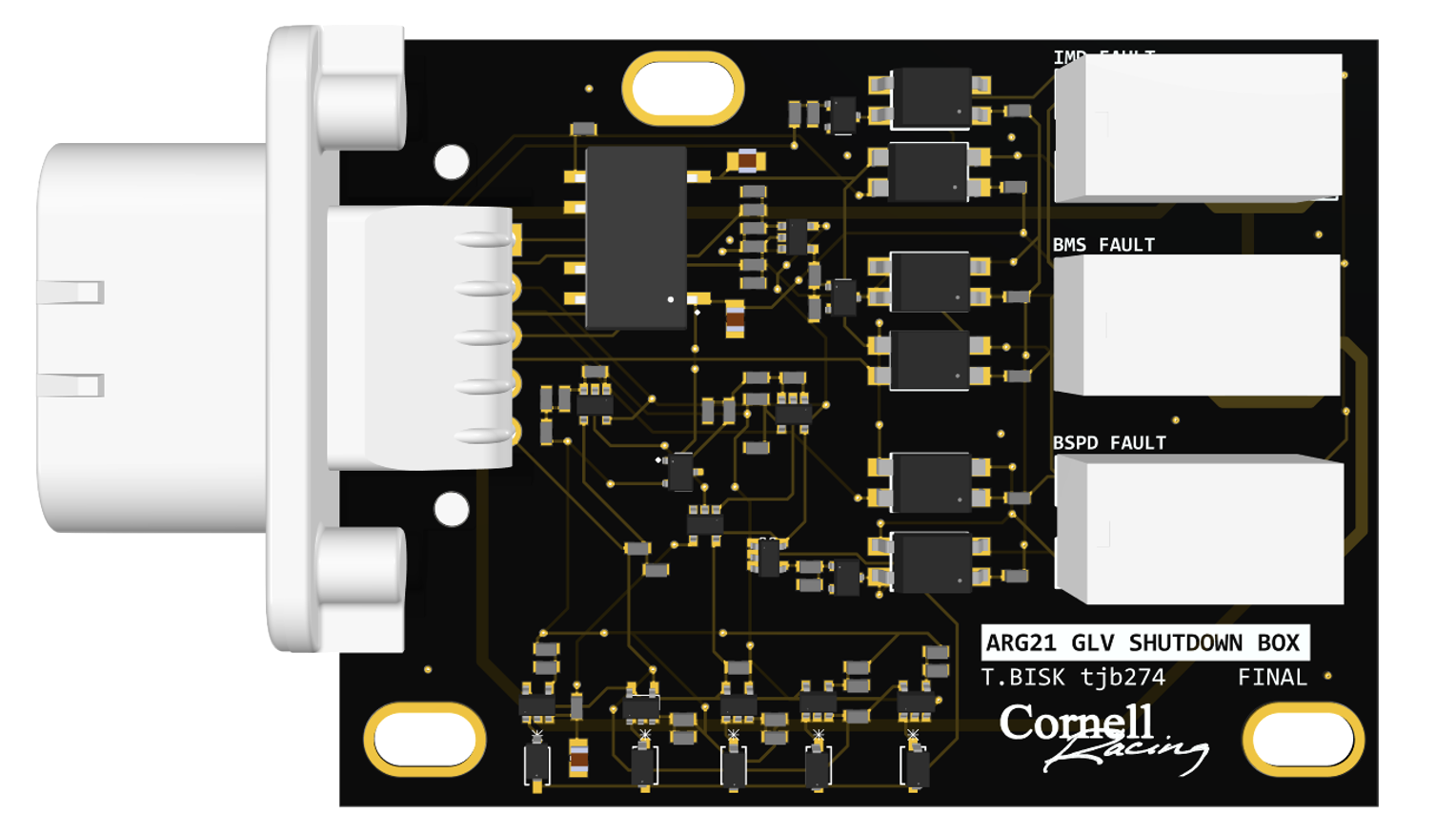
ARG21 Final Revision Designs
GLV Shutdown Box Top Level Schematic
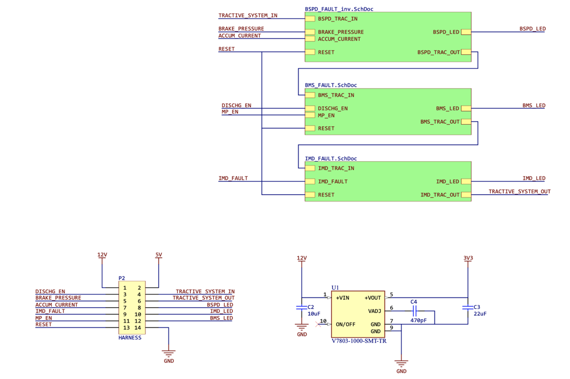
Seen above, there are three green boxes, each representing one latching circuit. They are wired in series, so that if any of the three latching circuits is opened, there is no current from TRACTIVE_SYSTEM_IN to TRACTIVE_SYSTEM_OUT. Each of these three latching circuits have the same logic to handle opening and staying open, but the logic before the relays looks quite different from one another and depends entirely on the fault being received. Each latching circuit has two normally open relays, one Single Pole Single Throw (SPST) and one Double Pole Single Throw (DPST), as well as a normally closed SPST relay to turn on an LED when it is faulted. Usually, when there is no fault, the DPST relay is closed and will remain closed, meaning there is a connection between tractive system in and tractive system out. When there is a fault, the N-Channel MOSFET prohibits current from flowing and therefore causes the relays to go to their “normal” states. This is open for the DPST, causing the shutdown circuit to open, while it is closed for the LED latch, causing the LED to receive power and turn on. The latches will remain in their normal state until the Normally Open (NO) SPST relay gets a reset signal causing it to close back up, restoring the circuit to the state that allows current to flow to and from the accumulator. Due to the way the circuit is designed, even when the fault is resolved the circuit still latches until the reset signal is received – functionality that is mandated by the rules.
Additionally, seen in the top-level, there is a 12V to 3V3 DC-DC converter that is used to power the LED signals.
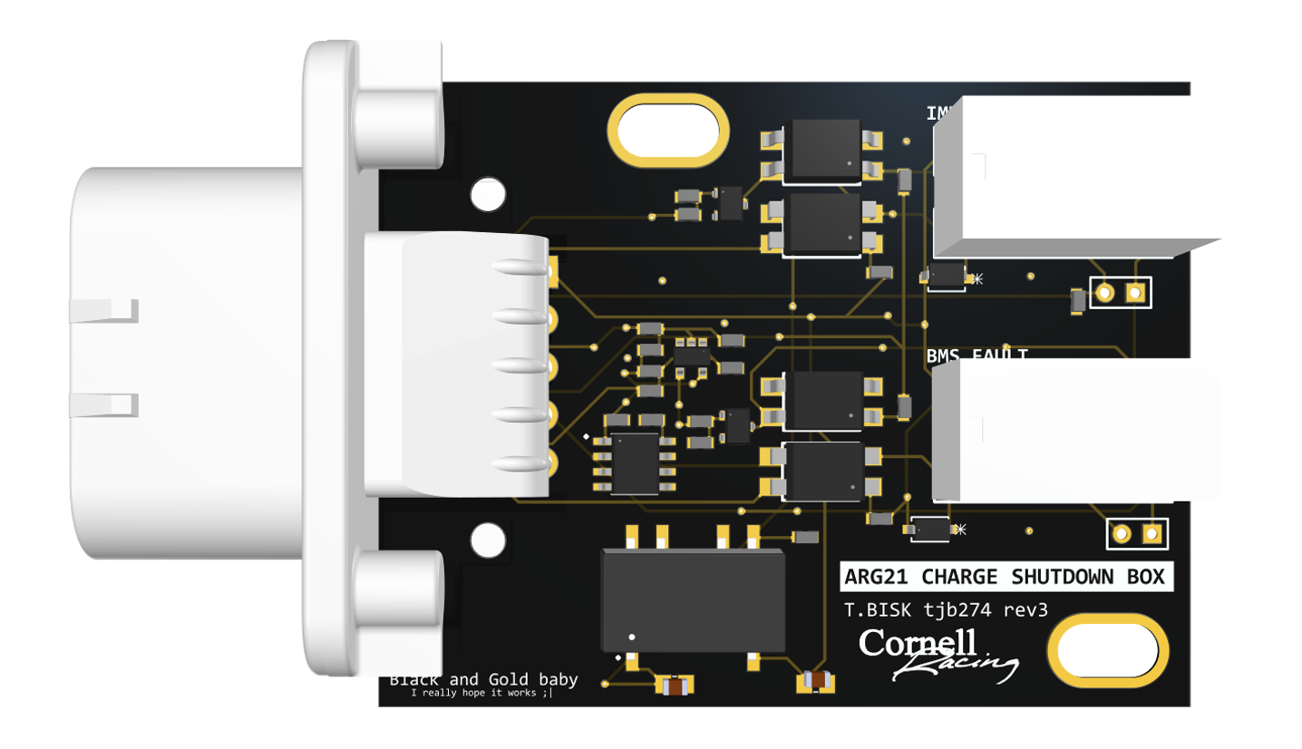
Charge Shutdown Box Top Level Schematic

The major differences between the GLV SB and the Charge SB is one, the fact that the BSPD is missing, two, that DISCHG_EN is replaced with CHG_SFTY, and three, the addition of a pull-down resistor at the end of the circuit. The motivation behind the resistor was EV.10.4.2.c, “the charger must be turned off” if there is a fault. After referring to the Brusa Technical Manual, it was evident that there was a pin to do just what we wanted called PON [6]. PON powers on the Brusa charger if it is high and turns it off if it is low [6]. Therefore, a simple fix to the board is to include a pull-down resister before the output of my board and connect that output directly to PON. This way, if there is a fault and the circuit is open, the resister will cause PON to be set to ground and thus turning off the charger.
IMD Fault
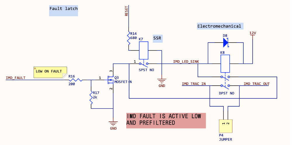
Of the three circuits, IMD fault is by far the easiest. There is a single fault signal for the IMD, making the logic straightforward. During normal operation the IMD outputs 10V which keeps the MOSFET opened, and when it is faulting the MOSFET closes which causes the shutdown circuit to fault as described above. No modifications have been made to this circuit since Rev 1.
BMS Fault
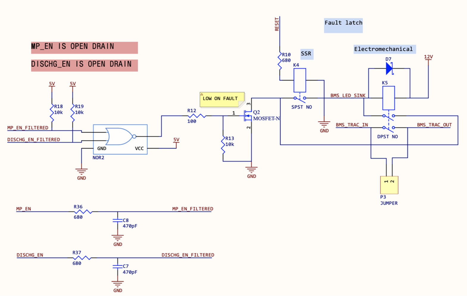
Before I began work on the Shutdown Box, the incorrect assumption was made that the BMS_FAULT signal was active high. Furthermore, only one general BMS_FAULT signal was assumed, when after analyzing the Orion BMS datasheet there are two different fault outputs on the Orion that pertain to our needs – not just one. These faults are open drain, so it was necessary to add pull up resistors to these signals. Since we want the signal on fault to be low when entering the MOSFET, I used a logical NOR gate.
There are many changes to the BMS fault since my previous revisions. The most noticeable of these changes is that the signals are now filtered. Since we are using a 2-input NOR gate, if any of these signals are high, there will be a fault. Two low-pass filters are used to filter out any unwanted high frequency (~ ≥ 500 Hz) noise that may potentially have an amplitude high enough to accidentally trigger the NOR gate.
The second change that was made from revs 1 and 2 was the voltage levels of the pull-ups and NOR gate power. The pull up resistors should have the same voltage as the power on the NOR gate, which must be between 2.5 and 6 volts per the datasheet [7]. Note that this is the GLV SB schematic but on the Charge SB the only difference is the names of the signals being filtered and thus going into the NOR gate.
BSPD Fault
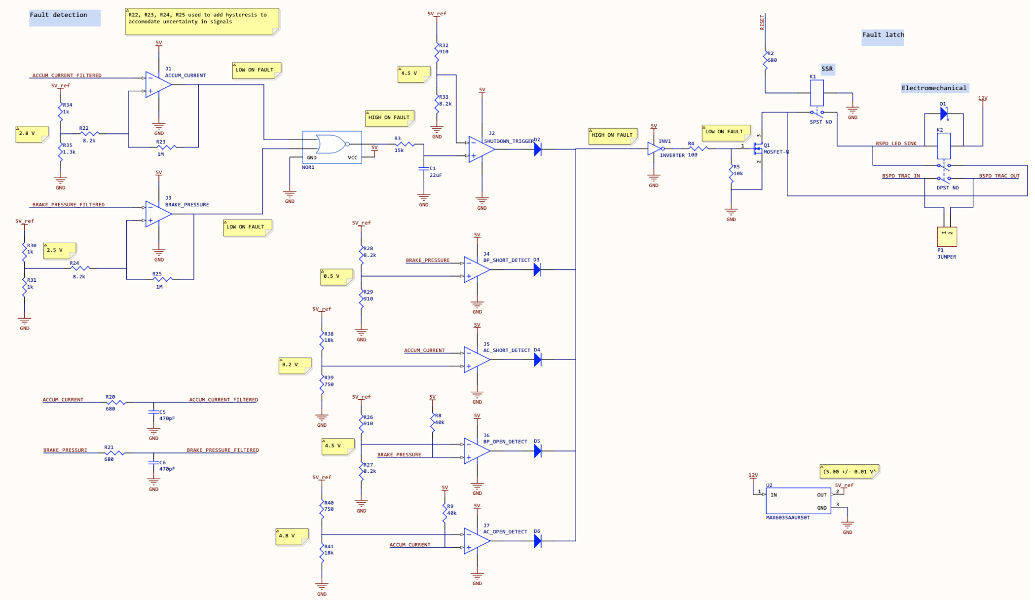
The BSPD must fault if both the if the brakes are pressed hard while 13.89 amperes of current are being drawn from the accumulator for more than 0.5 seconds, or if there is a short or an open in either of the two input signals. Since the signals are analog, comparators are used. They check to see if the input is above a certain value, and if so, the output of the comparator flips. There are seven comparators – four are used to check for open and short, two others are NOR’d together for the actual brake sensing plausibility. That output is fed through an RC time delay of 0.5 seconds which will trigger the seventh and final comparator, causing a fault. There is a diode OR which means that if any of the parts are faulting, the entire system will fault.
Since my previous technical report, the BSPD was completely redone. During janman, the BSPD was not operational even after debugging and changing things around for hours. The comparators and logic gates that were being used were way too small to bring up and test by hand. For my next revision I upgraded these components to be larger and more user friendly. Additionally, these new comparators are push-pull instead of open drain. This swap eliminates the use for pull-up resistors which decreases both the manufacturing time and the points of failure.
Even with the new components ready to be ordered, the data I was getting from testing was not lining up with expectation. As I began to understand the system more and more, it became clear to me that the issue was within the circuitry logic. The output of the diode OR really needed to be inverted afterwards to trigger fault if one or more of the diodes were reading a fault. Also, the RC delay was originally after the diode OR, which meant that there would be a 0.5 second delay even if one of the signals dropped. This shutdown has to happen immediately, so the RC delay and shutdown trigger was moved to before diode. It was experimentally determined that all of this had to be changed, since when testing the faults were inconsistent and backwards with what was expected.
Besides the actual change in logic, another obvious change that I made was the elimination of potentiometers. The combined use of comparators with potentiometers can be finicky especially when being put in a car that experiences lateral G forces. To avoid triggering the BSPD unexpectedly, I replaced the POTs with resistor that act as voltage dividers. To calculate the resistance, I looked at rules to find the cutoff voltage, then calculated the ratio of resistors to achieve that voltage in a voltage divider [8]. As discussed in the Data section, these values have yet to be experimentally verified.
After the potentiometers were eliminated, there were still three ways to improve: filtering signals, regulating reference voltages, and adding hysteresis to the comparators. The idea behind the comparators on the BSPD is that if the voltage from accumulator pressure signal and brake pressure signal are both higher than the threshold value for greater than half of a second, the car must shut down. Therefore, we need precision on that threshold value – it cannot be fluctuating or else we might shut down the car prematurely. I use a voltage regulator, U2, to ensure that the voltage in the voltage dividers being fed into the positive terminal of the comparators is 5.00 ± 0.01 V at all times. The signals themselves must also be filtered just as they are in the BMS Fault latch circuit. Fluctuations in the signals can also cause unwanted faults so I use another couple of low pass filters on the input signals to the BSPD to ensure that does not happen. A 0.1V hysteresis was added to the comparators J1 and J2. This was added because the device that is responsible of outputting ACCUM_CURRENT and BRAKE_PRESSURE specifies that amount of uncertainty. So, in order to be rules compliant while still accounting for the ±0.1V of uncertainty, hysteresis is added.
Testing
In order to set design criteria, the data needed comes from the fault signals. The shutdown box is three different latching circuits in series, so each of those three circuits are designed based on the type of signal coming in. So, to ensure that the datasheets of the IMD and the BMS are accurate, we must power the IMD and BMS respectively and determine what signal is output under specific conditions. When testing the actual board, we can simulate the signals from the IMD and BMS using power supplies. We can continually assume using the datasheets and experimental data that the fault signals are what we expect, so we can test using simulated signals as opposed to the actual faults from the IMD and BMS.
Simulating the BSPD is a lot more involved. Brake pressure and accumulator current are both analog signals. By rules, the BSPD must activate when braking hard but not locking the wheels, as well as delivering 5kW of power from the accumulator. Currently, we do not have a car to test the pedals with, so there is no certainty for what voltage level the signals will be when those conditions are met. I calculated accumulator current by doing 5000W / 360V = 13.889 A. The signal comes from the Current Transducer, whose datasheet says that 13.889A will be approximately 2.8V [2]. Therefore, I set the threshold voltage on my board using a voltage divider to be 2.8V. However, there is much uncertainty associated with this device, and it will take experimental data to prove this correct. To do this, we will send 13.889 amps out of the accumulator and measure the output voltage on the LEM using a multimeter. Additionally, we will need to test the output of the brake pressure sensor when we are braking but can still spin the wheel by hand. It is essential that these numbers are correct because they are verified at tech inspection during competition.
The idea behind testing is to first ensure each of the circuits open and close under the correct circumstances and stay latched until RESET is pushed. Secondly, we must ensure that the corresponding LEDs are outputting as expected. When there is no fault, we expect the LED output signal to be floating. When a fault does occur, the LED signal should be 3.3V.
Testing can be divided into three sections. The lower the priority, the more important it is.
- Testing the boards themselves with the assumed fault signals to ensure that it is opening and closing the shutdown loop expectedly.
- Priority level 0
- If the board does not actually cut power to/from the accumulator when it could result in catastrophic failure
- Testing the brake pressure and accumulator current signals to verify values
- Priority level 1
- Inaccurate values may result in us failing tech, but the values are very easily adjusted by replacing resistors, and the error likely on the order of decivolts
- Testing the IMD and BMS faults
- Priority level 2
- The team is very confident that these work as expected
Continuations
If there were more time in the semester, I would have spent more time optimizing and organizing the layout of the board. I have gotten the schematic to where I like it, but board bring up could be made less challenging with a more organized layout. If there were more time, I would have liked to test whether it was necessary to have the 5V vref on the GLV SB or if the 5V signal generated from the Fusebox is steady and precise enough to not affect the BSPD in a negative way.
Next year’s board designer should potentially recombine the boards into one. The way that the charge shutdown circuit was wired this year warranted two boards, but if next year’s board designer works with powertrain, we can eliminate the need for two boards by standardizing pins and simply shorting over the BSPD when charging.
References
[1] Orion BMS, “Wiring & Installation Manual,” Carol Stream, IL, 2018.
[2] LEM, “Automotive Current Transducer DHAB S/124,” 2016.
[3] Bender GmbH & Co. KG, “ISOMETER IR155-3203/IR155-3204,” Gruenberg, Germany, 2018.
[4] N. Lin and J. Gao, “ARG20_Fa19_TechnicalReport_Electronics_Control_Unit_jg992_nl392,” 2019.
[5] TE Connectivity, “AMPSEAL 14 POS RIGHT ANGLE HEADER ASSY,” Schaffhausen, Switzerland, 2020.
[6] Brusa, “Technical Data and Startup,” Munich, Germany, 2012.
[7] Texas Instruments, “Single 2-input Positive-NOR Gate,” Dallas, Texas, 2003.
[8] T. Bisk, “BSPD Calculations,” Ithaca, NY, 2021.
[9] N. Lin, “ARG20_Sp20_TechnicalReport_Electrical_ECUSBFW,” 2020.