Introduction
Using a PIC32 microcontroller, a DAC, a keypad, and a speaker, we were able to create a system to generate sounds identical to the ones made by the northern cardinal. Pressing ‘1’ on the keypad generates one note of a song (swoop), ‘2’ generates another note (chirp), and ‘3’ 130ms of silence. The system can also record a song consisting of a series of notes and silences to be played back later.
Design and Testing Methods
Concept
Our end goal is to generate songs using swoops, chirps, and silence notes to mimic songbirds. We first attempted to generate a sine wave at target frequency, by sending the correct data to the DAC to control the output on the speakers. We then integrated the keypad example code on the course website, and generated a sound on any keypress. Then using the algorithm described on the course webpage, we generated a swoop on the ‘1’ keypress and a chirp on the ‘2’ keypress, and implemented a silence note for the ‘3’ keypress. We sketched out a state machine for the debouncing algorithm, and implemented it. Finally, we implemented the play and record modes to enable song recording and playback. We aimed to achieve good modularity and testability with our approach, making small incremental changes and testing for controlled, specific results.
Hardware description
Materials
- PIC32 and Power Cable
- pickit 3 + USB cable
- breadboard
- 330 ohm resistors
- keypad
- SPDT switch
- audio socket
- aux cord
- speaker
- wires
Setup
Figure 1: The Hardware System-in-Progress
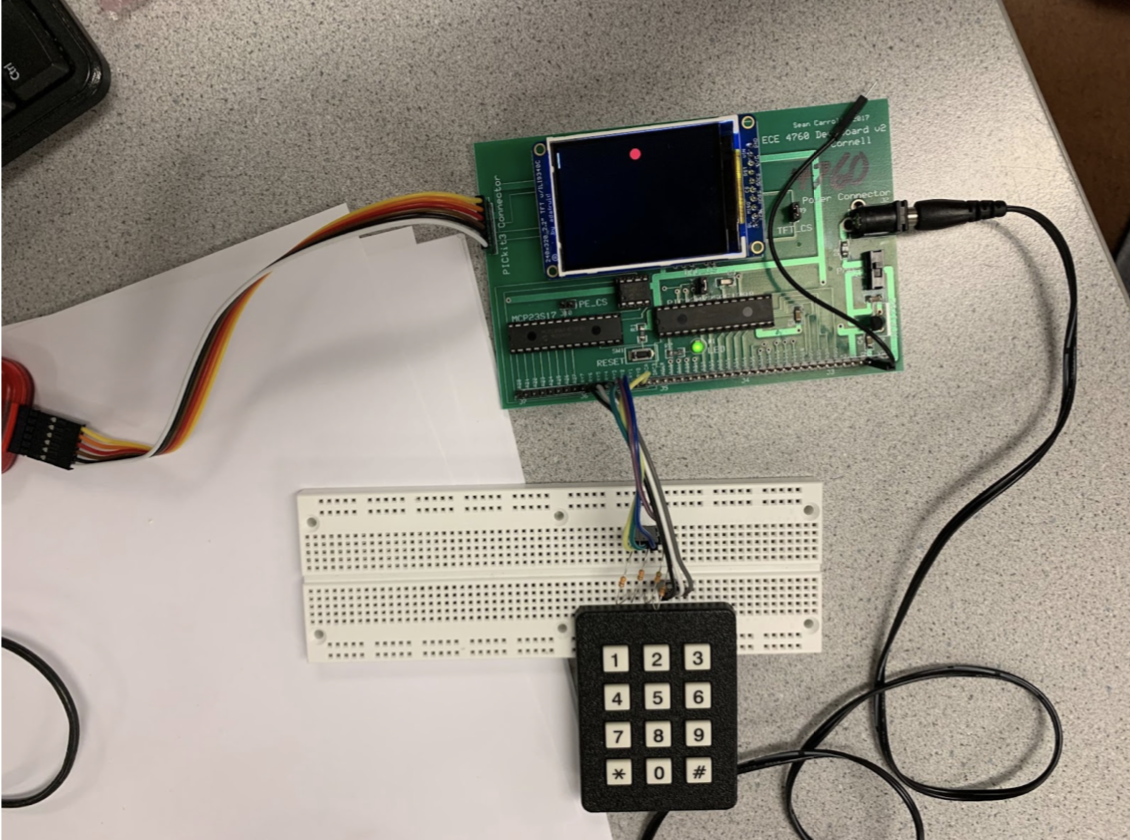
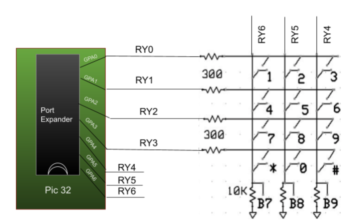
The ECE 4760 PCB is the center of attention. It includes a PIC32 microcontroller, a DAC, a port expander, and a TFT display. The PCB is given power using the power cable on the right, and firmware is flashed to the PIC32 using the PICit3 (the rainbow wires on the left). On the bottom shows the keypad with its resistors connected to the port expander. When a button is pressed, one column is shorted to one row. Resistors are required on the rows so if two buttons are pressed the outputs are not shorted. The table and schematic below shows how the keypad was wired to the port expander.
Figure 2: Pinouts for the Keypad/Port Expander
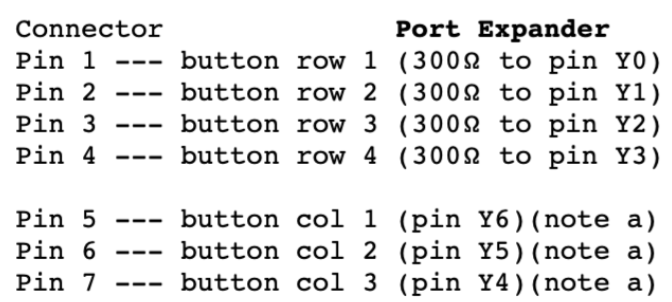
Figure 3: Circuit Diagram / Schematic of Keyboard to Port Expander on Pic 32
Once the desired sound was calculated, it was output on DAC_A. Using an audio socket like the one pictured below, DAC_A was wired to the rear pins and the front pin was connected to ground. Then, a speaker was plugged into the 3.5mm jack and sound could be heard.
To toggle between record and play modes, a single pole double throw switch was placed on the breadboard. Then, the left pin was tied to ground and the right side tied to +3V3. Finally, the middle pin was wired to RB0. This wiring allowed for RB0 to read a digital 0 when the switch was in the left position, and for RB0 to read a digital 1 when the switch was in the right position.
Software Description
Our starting point for our system is the DDS_Accum_Expander_BRL4.c example code on the course website, making use of the DAC, port expander, TFT display, system interrupts, Protothreads, and a software keypad decoder.
We programmed an ISR to generate audio at a 44k sampling rate, so on a 40 MHz timer, we generated interrupts every 909 cycles. Our ISR calculated the next amplitude based on the note to generate encoded by a global volatile variable (named button). The algorithm we used to calculate the correct frequency is outlined on the course website. We increment our phase accumulator variable, DDS_phase, by a certain amount for each audio sample generated, or during each interrupt of the ISR. Since we allow our integer accumulator to overflow as an input to the sine function and we generate audio samples at a certain rate, Fs, we scale our target frequency, Fout, by 2^32 / Fs, to get our phase increment per interrupt. For the swoop, the target frequency vs. time graph is modeled as the top half of a sine function, and for the chirp, the graph is exponential (which we calculated by multiplying, rather than using a square or power function). We took care to transform our time variable note_time to generate exactly half a period for the swoop, using the pi_time constant. We also applied a linear ramp to each note to avoid popping sound caused by large jumps in the DAC output amplitude. The number of cycles used to calculate and send out the current amplitude must be at most 909 minus the cycles needed to context switch, so we used a sine lookup table with 256 entries instead of the math sine function. We also precomputed all constants and used the fixed point data type __Accum where possible. To communicate with the DAC, we complete SPI transactions at the end of the ISR with the output data.
Figure 4: Debouncing Finite State Machine
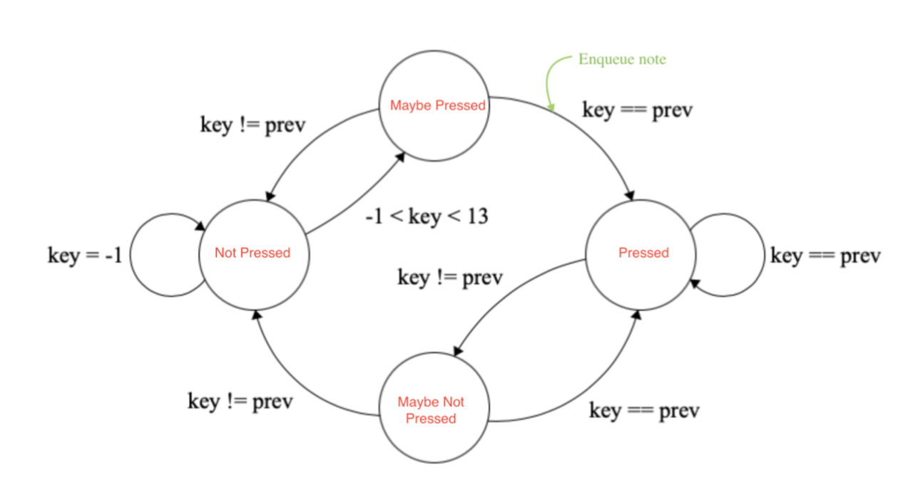
Figure 5: Amplitude Modulation Envelope of a Chirp
The timer thread updates the seconds since boot on the TFT using a while loop and a millisecond yield. We did not change this thread from the example code. The key thread sets up the GPIO pins for the keypad, listens and decodes a keypress every 30 msec, and draws the key pressed on the TFT display, as in the example code. We added an implementation of the debouncing algorithm, adding the key pressed to an array if in record mode or setting the button variable accordingly in play mode. The mode is encoded by a defined variable named mode reading an input pin connected to the physical switch, where 0 signifies record and 1 signifies play. When in play mode, the sound thread sets the button variable when the next note is to be played from the queue of recorded keypresses, that is, when note_time reaches 5720. The thread yields when not in play mode, or if the recorded song playback is over.
Testing
When it comes to testing audio synthesis, one can easily test the system by simply listening. We compared the sounds generated by our system and compared them with the synthesized and authentic cardinal samples on the course website.
If it sounds right then, it is right. - Hunter Adams, 2021
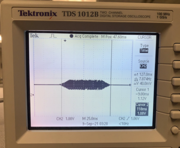
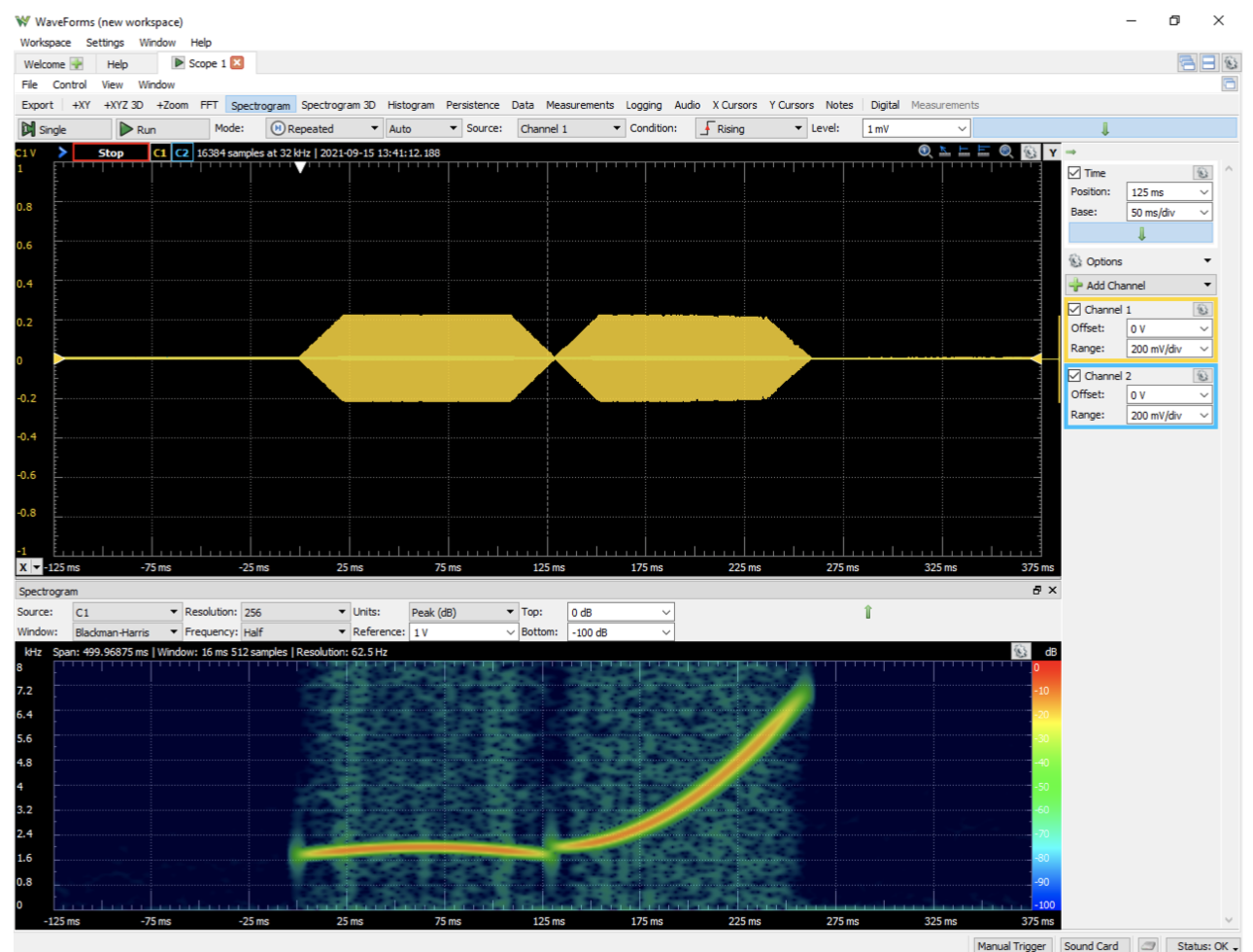
We also performed a quantitative assessment of the sounds generated, by attaching an oscilloscope to our DAC channel. We checked the frequency output of the swoop and the chirp, and matched it against the expected values. We also generated a spectrogram using the lab computer, by outputting our audio to the lab computer microphone jack, we used Waveforms to capture and compare the spectrogram of our audio synthesis with the expected one.
Figure 6: Spectrogram of a Swoop-Chirp using WaveForms
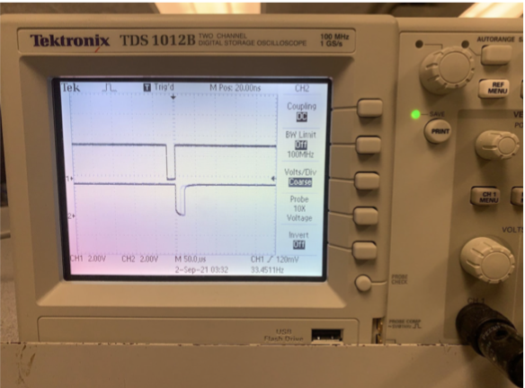
To test our debouncing algorithm, we held down our keys and clicked them as fast as we could to ensure that only one sound was played at a time. That is, we ensured that subsequent keypresses or holding down a key did not cause a sound to interrupt the current sound that was playing.
Figure 7: Oscilloscope Reading of a Keypad Press
To test our play and record modes, we ensured that pressing keys in record mode did not generate sound, and that the sounds that would be generated were played back in the same order that they were pressed in record mode. We first tested with a cardinal song, recording and playing back two swoop-chirp-silence triplets (1-2-3 on the keypad). We were also able to hear and see in our spectrogram that each note was played for the correct amount of time. In play mode, we ensured that the playback recorded in record mode was played, and that pressing keys would generate sound, also subject to the debouncing algorithm.
Results
The result of this lab was two audio outputs. More concretely, It was a swoop that emanated from 1.74kHz, peaked at 2kHz, and descended back down to 1.74kHz within a time frame of 130ms and a chirp that began at 2kHz and ascended in quadratic fashion all the way to 7kHz in a timeframe of 130ms. There was an error of just 0.67 Hz which arose from our use of 2^32 for our direct digital synthesis accumulator [2]. Additionally, to mitigate unnatural clicks, the swoop sound was amplitude modulated with a linear ramp function. This amplitude modulation allowed for the amplitude to smoothly rise from 0 to its max amplitude and then fall back down to zero when the note was almost over.
The main output and goal for the system is a birdsong. Printing to the TFT, like the key that was pressed and the time since boot is bonus information that is not necessary in the end product and really just for debugging purposes. The system itself was accurate to the point where a human could not discern a difference between the sound generated by a synthesized birdsong and one of a northern cardinal in the wild. The bird synthesizer was fast enough that one could press the buttons as fast as possible and there would be no unwanted extra presses (bounces) but also no instances where a button was pressed and it was not counted.
Quantitative data from our spectrogram in Figure 13 shows that our song did indeed output the expected frequencies for the correct amount of time. Figure 13 also shows the amplitude modulated envelope. Qualitative data from this project is that we could record songs for “as long as we wanted” and they always sounded “correct” when we played them back. The TAs attempted to break our system by flipping between modes, mashing the keypad, and unpredictably hitting reset, but the synthesizer prevailed and refused to be broken. It was extremely reliable. The TFT always showed the most recent key press with no delay.
Our code played back sound at a rate of 40kHz. With a clock speed of 44MHz on the PIC32, that means interrupting every 909 cycles to play the next frequency. At first, we had floating point calculations inside our ISR which eventually slowed down and crashed the entire system. Using the TFT to debug, we printed how much time was being spent inside the ISR. Whenever a swoop was sent, the ISR took over 800 cycles to complete the calculations, which was ultimately the cause of our issues. After replacing some #define statements with variable declarations and doing as many calculations outside the ISR, we were able to optimize our ISR to take just 350 clock cycles no matter what button was pressed.
Conclusions
In the end, the project did exactly what it was supposed to do from the highest level: it is able to generate a swoop and a chirp and can also record such sounds and play them back. The debouncer effectively prohibits unintentional button presses and the amplitude modulation creates smooth, pleasing-to-the-ear sounds.
In doing this lab, we were introduced to the large world of optimization. It was essential to do calculations as quickly and efficiently as possible, whether that mean avoiding floating point calculations or choosing sizes for our sine lookup table and size and types for our array of notes to be played when recording. Learning this now is especially important when looking ahead to the next project, boids, which is essentially a lab all about optimization.
We also learned about the direct digital synthesis algorithm and how different amounts of precision can arise from using different-sized accumulators (8, 16, and 32 bits), but the sine lookup table does not need to be nearly as long. We also learned the importance of drawing out a complicated state machine like the debouncer on paper before trying to code. The fact that we had spent time drawing and thinking about what we wanted our code to do allowed us to move faster and create error-free code when it came down to it.
The major issue that was faced was doing floating point calculations inside the ISR. It was difficult to reproduce the problem at first because it felt as though our system would just gradually slow down and stop even though initially it worked perfectly. In order to debug this, we printed to the tft how many cycles were being spent inside the ISR. We quickly understood that it cost ~800 cycles to calculate the next note for our chirp which was way too much. Doing unnecessary calculations outside the ISR (and replacing #define statements with actual variable declarations!) saved us over 400 clock cycles and left us with a bird synthesizer that did not crash no matter how quickly it was pressed.
To a user who is not familiar with the project, the usability of the birdsong synthesizer may be a bit challenging. The user is faced with just a bunch of buttons and a switch, but nothing is labeled. To stay consistent with using hardware control for this lab as opposed to a python interface, it is possible to add a label under the switch that says ‘play’ and ‘record’ mode. Also, instead of ‘1’ ‘2’ and ‘3’, labeling the buttons as ‘swoop’ ‘chirp’ and ‘silence’ would be a big help.
An improvement that can be made to our implementation is the fact that we used a busy wait instead of a PT_YIELD_UNTIL(pt, condition) when playing back a recorded sound. We were able to get away with a busy wait because our implementation only had two threads: a sound thread and a buttons thread. If there were to be a third thread that is ready, it would be a good idea to yield the sound thread in between notes so other threads can run even while playing a long song.
References
[1] ECE 4760 Course Staff, “Wiring the keypad”, N.D. Available: https://people.ece.cornell.edu/land/courses/ece4760/PIC32/index_keypad.html, accessed September 10, 2021.
[2] H. Adams, “DDS”, N.D. https://vha3.github.io/DDS/DDS.html accessed September 17, 2021.