Objective
- Communicate information wirelessly over RF
- Navigate an unknown maze in order to discover treasures
- Enable robot when a specific note in a melody is heard
The Hardware
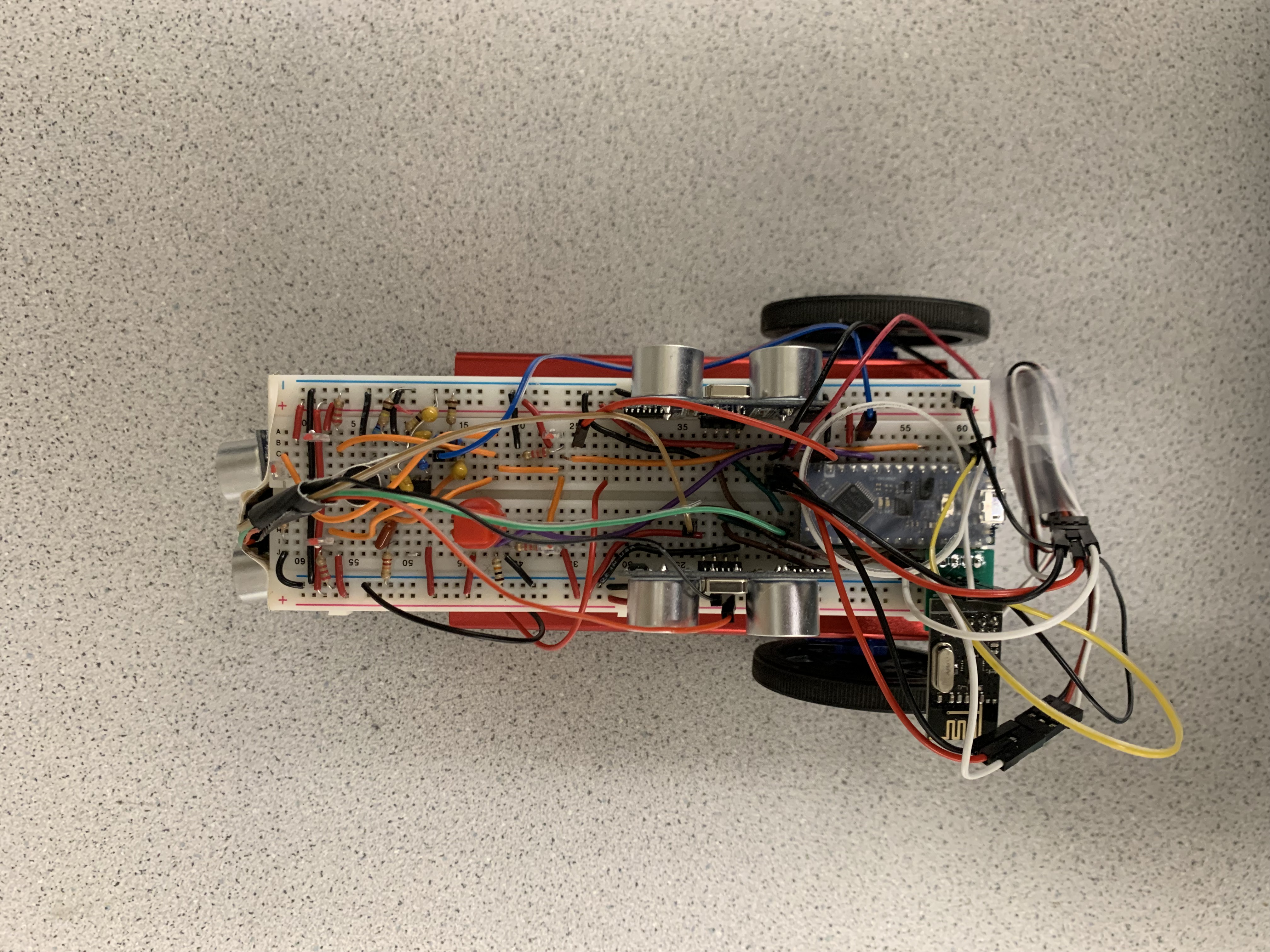
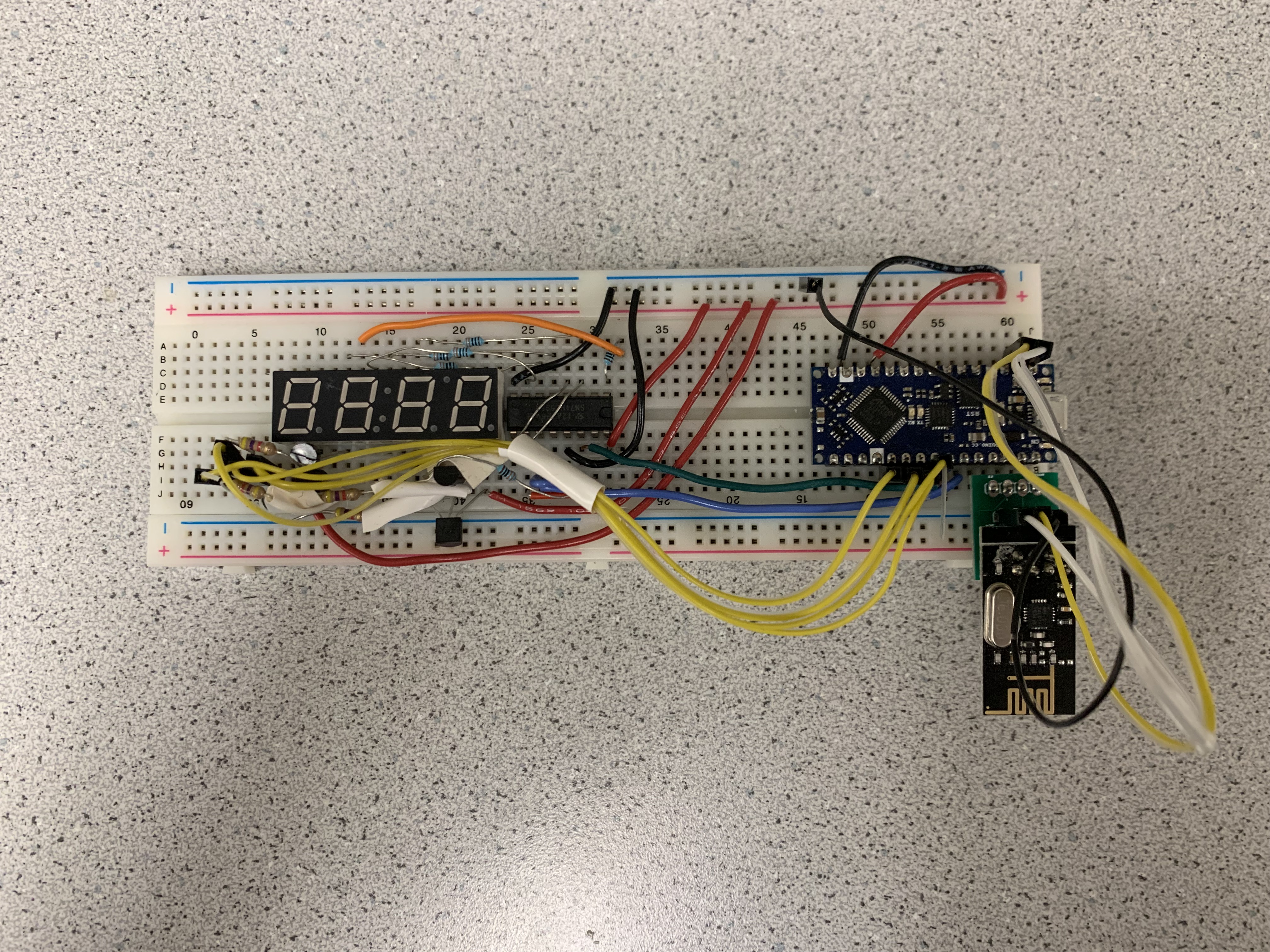
By the beginning of part 4, the robot already had all the necessary hardware for navigating a maze, detecting treasures and walls, and generating an FFT using a microphone. The base station already could output given unsigned ints (range of 0 - 65,535) to the 7-segment display. Now, to tie the two together, we needed an RF transceiver to transmit and receive data between the two. The transceiver is affixed to a PCB with soldered headers, as shown in Figure 1.
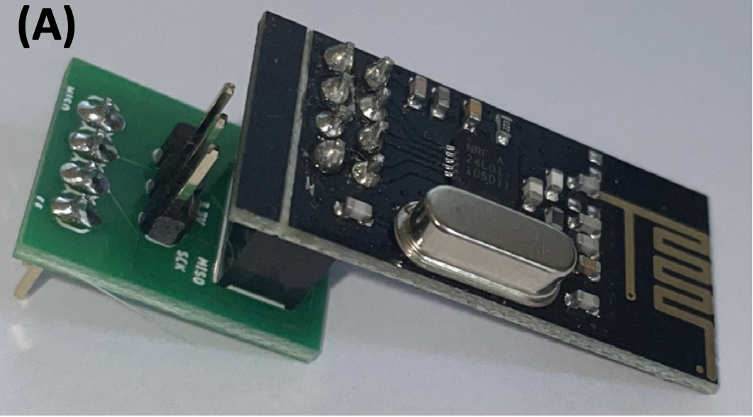
The four pins on the nano being used that are directly connected when sticking the PCB into the breadboard are D9-D12 for SPI communication (CS, CE, MOSI and, MISO respectively). Jumper wires are then used to connect the transceiver to the 3V3, ground, and SCK pins on the nano. Now, when the process is repeated again on the base station, the nanos can transmit data wirelessly to one another.
The FFT
The first thing that needs to happen in the demo is the robot must begin moving when it hears a 950 Hz tone. It sits ans waits at the beginning of the maze until such a noise is heard. We already had code from part 3 to generate an FFT, so using that code we generated a plot of a 950 Hz signal.
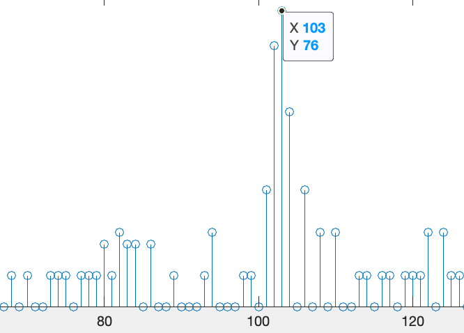
From visually inspecting the results, it is clear that bin 103 corresponds to 950 Hz, with not much frequency content outside of bins 102-104. Therefore, in our final demo code, we generate an FFT and check to see if bin 103 is above a certain threshold. If it is not, then throw away the results and take another FFT. If it is, then we must completely disable the FFT code and its interrupts, then setup the servos, ultrasonic sensors, RF, and phototransistors. Failing to do this crucial step results in sensor readings that are either way too high or too low and possibly servos that do not behave as expected. We debugged this issue by commenting out lines of our FFT code until the sensors behaved as we expected, then restored registers to what they were after hearing a 950 Hz tone before proceeding with Navigation.
In the event that our robot does not hear the sound, we have an FFT Override button. The button is a normally open button with a pull down resistor. When the button is pressed, the signal goes high and we add another condition to our FFT start the robot statement that checks if FFT_OVERRIDE_PIN = 1. FFT_OVERRIDE_PIN can be any unused digital pin on the nano.
The Navigation
PID
We spent the most time on navigation because there are a lot of moving parts (literally). For our final demo, we used PID when moving forward to keep the robot in the center of the maze. Lots of time was spent adjusting the values of PID that would consistently result in robot that could handle getting a few bad sensor readings in a row without crashing. This was more difficult than it seems because if the robot makes too big of a correction then it will no longer be pointed perpendicularly to the wall and the sensor readings will get larger-than-expected values. Then, the robot gets turned even further from the wall and ends up crashing in a positive feedback loop. We were able to mitigate some of these errors by stopping for a second (non-blocking) if the sensor reads something that does not seem quite right. Additionally, we put a cap on the maximum amount that the robot can turn at a time so it is never too far from perpendicular.
Turning
An advantage our robot had over other robots is that we used the ultrasonic sensors to turn 90º instead of timing it out, which is highly dependent on servo calibration. When we turn right, for example, after the robot has turned away for a few milliseconds we begin to sense for the left sensor to read a value determined by how far away the front sensor was from the wall when it began turning. This implementation worked pretty well and the robot consistently turned about 90º. It worked so well that Carl took a video of it in action.
Navigation Algorithm
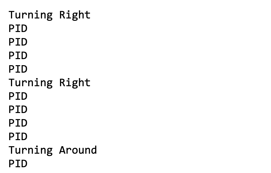
As described above, our robot could go straight and could turn left, right, and turn around. The final piece of the puzzle was to design some sort of algorithm to ensure our robot would hit every square in the 5x5 maze. At first, DFS seemed like the best choice: it guarantees that the robot would get to every square in a timely manor. The servos and the sensors were inconsistent enough that it was very difficult to keep track of what square the robot was in to execute DFS. Based on the constraints for the maze, turning right any time that we could was a viable alternative. Therefore, the order of priorities for navigation became turn right, go straight, turn left, turn around.
The Treasures
The code and method for detecting treasures is exactly the same as it was in part 2 using analog compare and phototransistors. However, in part 2 the communication of a detected treasure was done via the serial monitor, whereas in part 4 we must use our base station to display the treasure frequency. Using the built-in Arduino RF library, we can simply swap out a print statement for an RF statement. In order to make sure our robot and base station are paired, we set the pipe numbers accordingly. Our robot sent data on pipe 8 and received acknowledgements from the base station on pipe 9.
On the base station, the number_to_display to the 7 segment display is no longer a constant, but instead an unsigned int that is set by the packet (the treasure frequency) received via RF. When the robot is not detecting treasures the robot is not sending any packets, so the frequency is displayed on the base station until the robot sees another treasure.
The LED
When the robot finds two distinct treasures (two treasures whose frequencies are greater than 999 Hz apart), it has finished the maze. We signify this result by stopping the servos and blinking the on-board LED. The on-board LED is D13 on the nano, which is also being used for RF. Once we disable RF, it is possible to use non-blocking statements to write high and low to input D13 every 500 ms to blink the LED at 1 Hz. We were able to test this using a function generator wired to an LED, as in part 2.

The Demo
At the demo we demonstrated all of the hard work we had put into the project. Our robot jumped into action as soon as the appropriate note in ‘happy birthday’ was reached. Then, although the robot hit 3 walls throughout its journey, the robot navigated to every square of the maze rather quickly. Carl was so impressed that he took a video of it in action. It was very rewarding to finally get to the demo after 5 or 6 weeks of hard work on part 4 alone, plus the work done in parts 1, 2, and 3.
Video of Final Demo
Resources
[1] C. Poitras, RF Communication, Navigation & Finalizing Robot – Final Demo, ECE 3400, November 1, 2021.