Objective
- Build and test an infrared light detection circuit
- Use the Arduino Nano to characterize the infrared signals
- Breadboard and test a 7 Segment Display
The Phototransistor
A phototransistor uses light to modulate how much current passes through it. In this part, a voltage divider is implemented using a phototransistor that can sense infrared light. By placing a phototransistor and a resistor as the top and bottom halves of a voltage divider, an analog signal is generated. The higher the voltage read on A1, the more IR light is hitting the transistor.
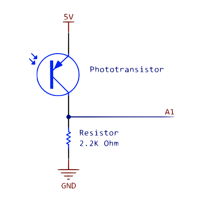
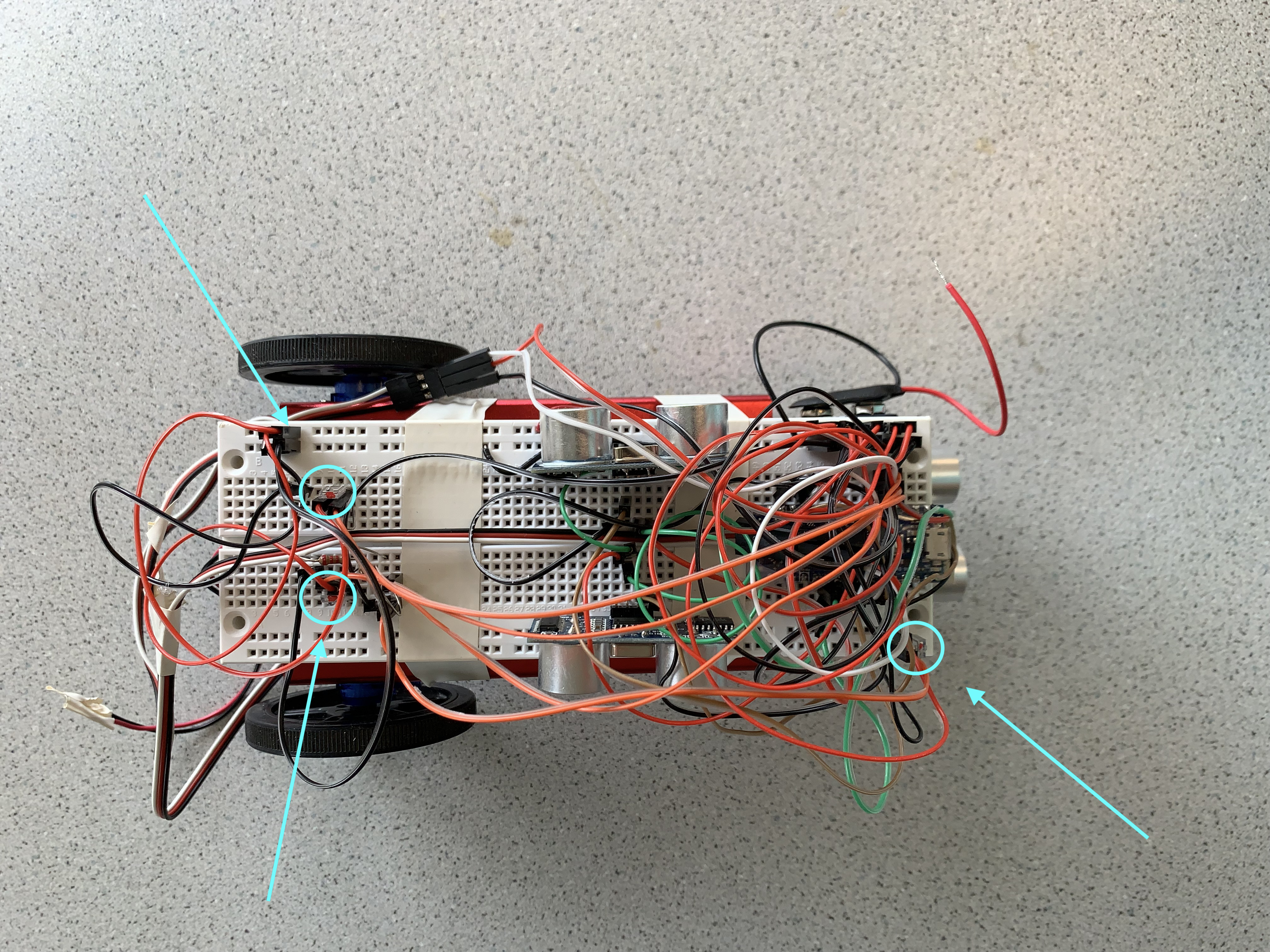
The first of the phototransistors points to the front of teh robot. Two additional phototransistor circuits were added, pointing left and right, so light can be sensed from any direction without the robot phyically turning. All three phototranistors output to A1 on the Nano.
The Infrared LED
Next, an IR LED was connected to a function generator. In order to limit the current passing through the LED, the LED was wired in series with a resistor. The maximum current flowing through the LED ought to be 20mA, so at 1.2V, a 62-Ohm resistor was selected (62 Ohms >= 1.2 / 0.2).
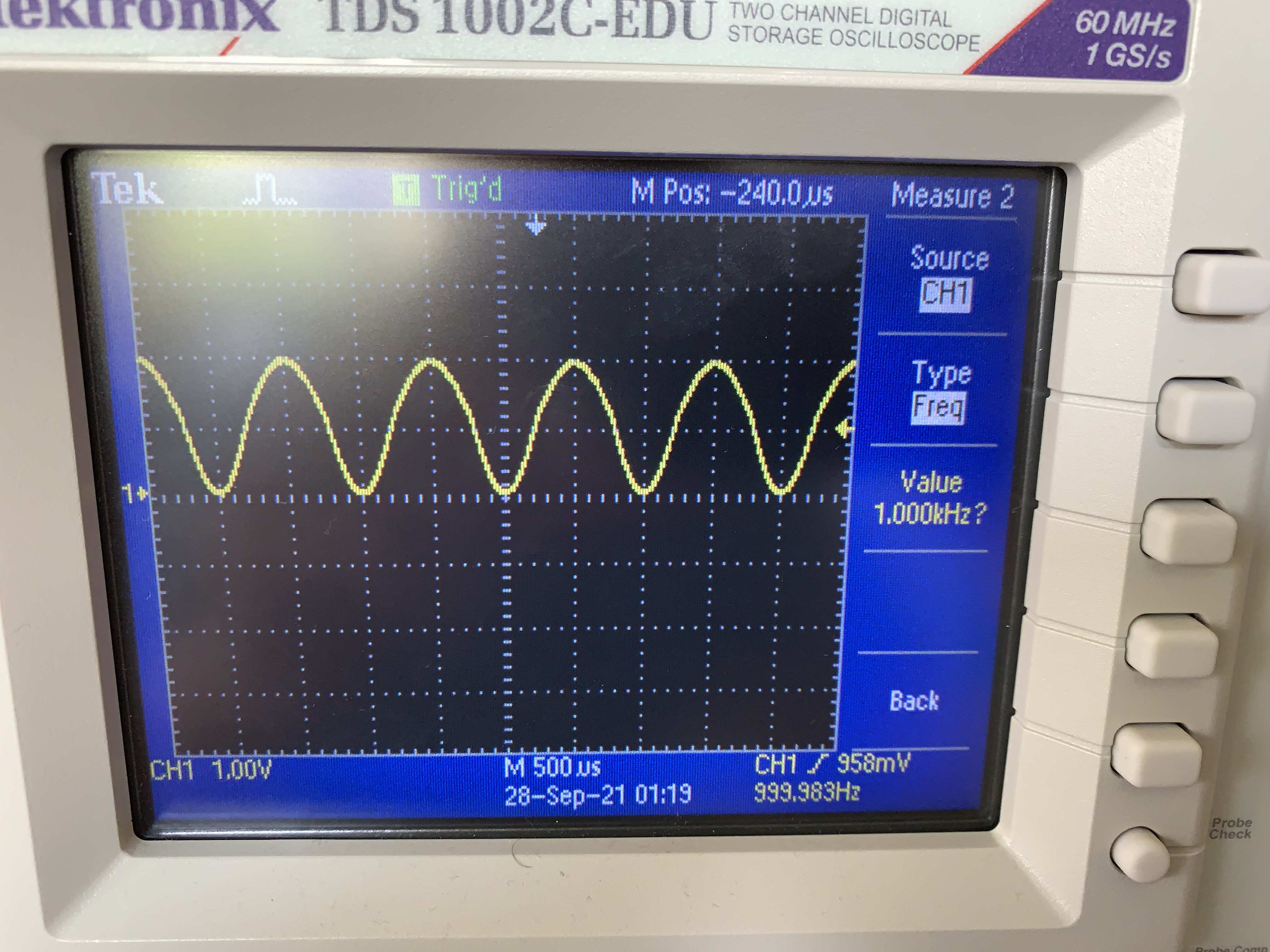
The function generator was programmed to output a sine wave of frequency 1000 Hz at an amplitude 1.2V peak-to-peak. An offset of 0.6V was added so the voltage never goes below 0 Volts. In order to make sure everything was wired correctly, the probes of an oscilloscope were connected across the entire series circuit. The resulting waveform was a perfect sinusoid with frequency 1kHz. The amplitude is not exactly 1.2V because the impedance from the function generator does not equal the impedance from the oscilloscope, but for this exercise, we only care about frequency and shape so it is not an issue that needs to be corrected.
Testing the Phototransistor
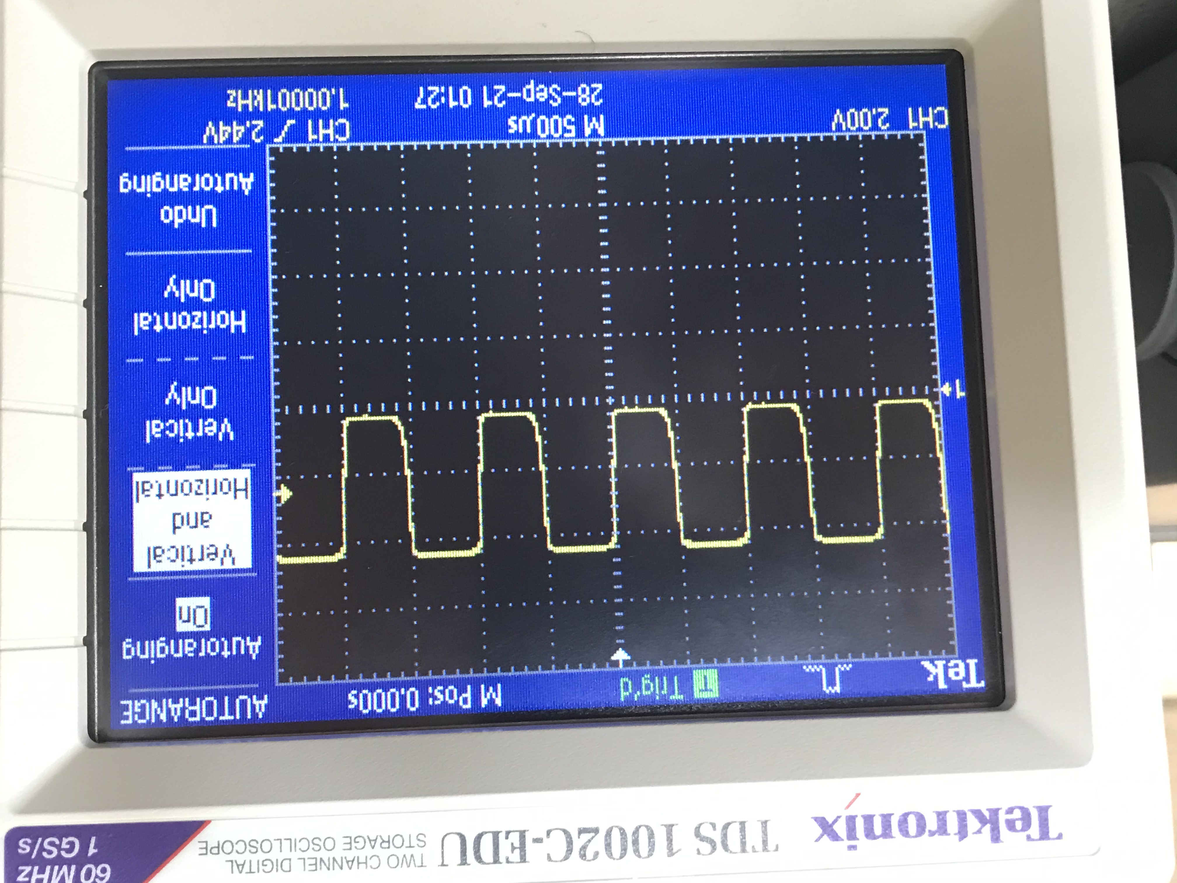
Finally, with both the phototransistor circuit and the LED circuit fully connected, the phototransistor could be tested. The probes of the oscilloscope were connected across the resistor going from A1 to ground. When the phototransistor was pointed directly at the IR LED, the oscilloscope read a 1kHz signal, which demonstrated that the phototransistor was functional. The wave was more square than sinusoidal because there is some amount of response time associated with all transistors.
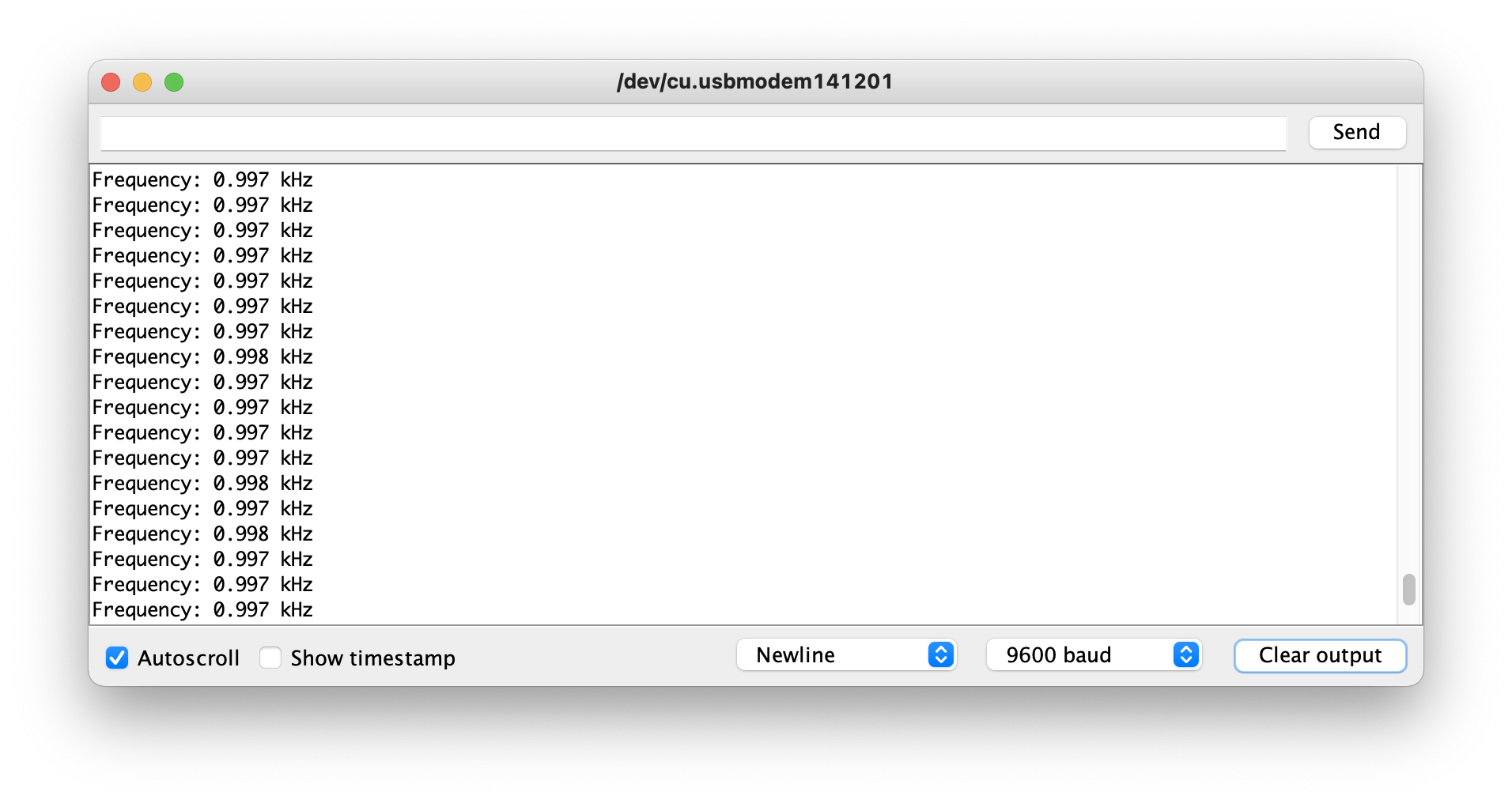
It can be seen in the bottom right corner of the image that the function generated has a frequency of 1000.0 Hz.
Code was then flashed to the Arduino to calculate using the ADC and the DACREF what the frequency of the blinking light is. Then, the calculated freqeuncy was sent to the serial monitor. The threshold for the DACREF is dependent on the amount of ambient light in the room.
The Base Station
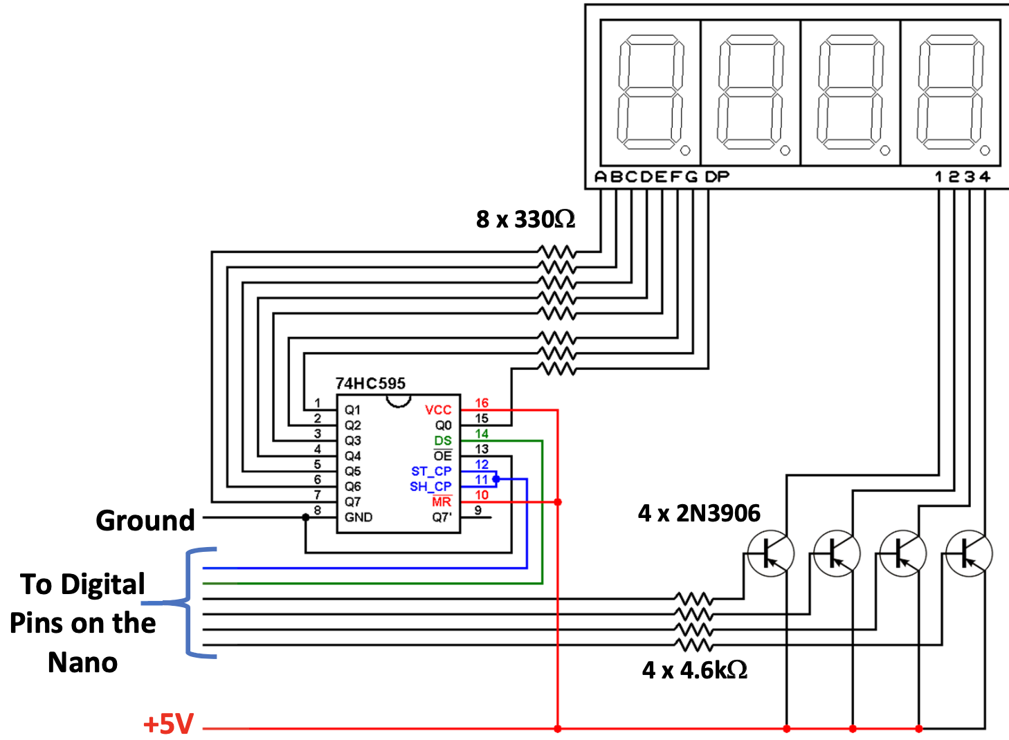
The beginnings of the base station, which was introduced in part 2, included a 7 segment display, a shift register, and a second Arduino Nano. Since there are 4 digits on the 7 segment display, it would require many digital pins to light up the entire display at once. The shift register allows us to illuminate one digit at a time in rapid succession while still having pins to spare on the Nano. This part of the project was spent breadboarding and relied on our knowledge of circuits. The code to display a given integer was provided.
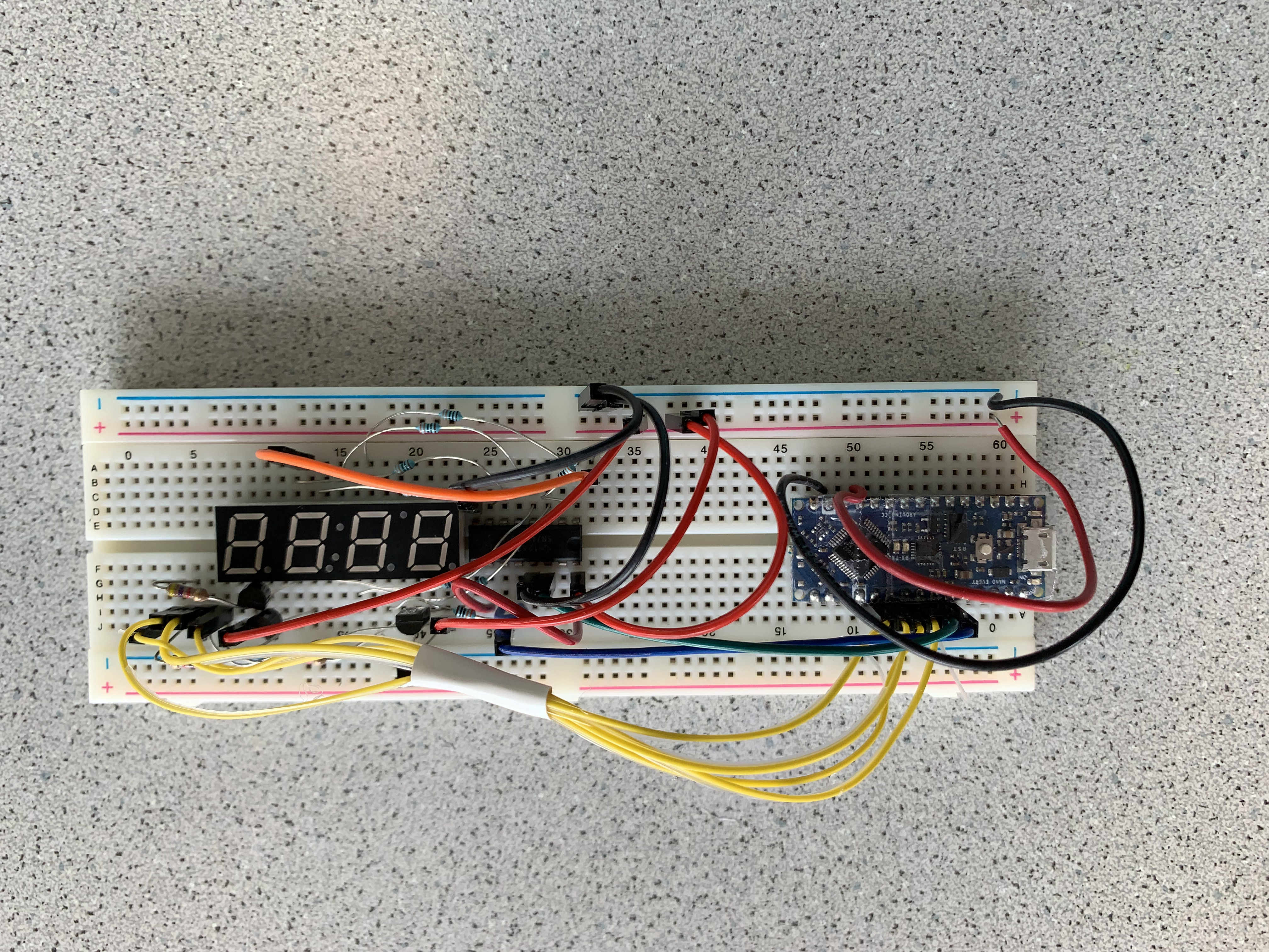
Testing the Base Station
After managing to completely replicate the schematic, it was time to flash the firmware to the base station.
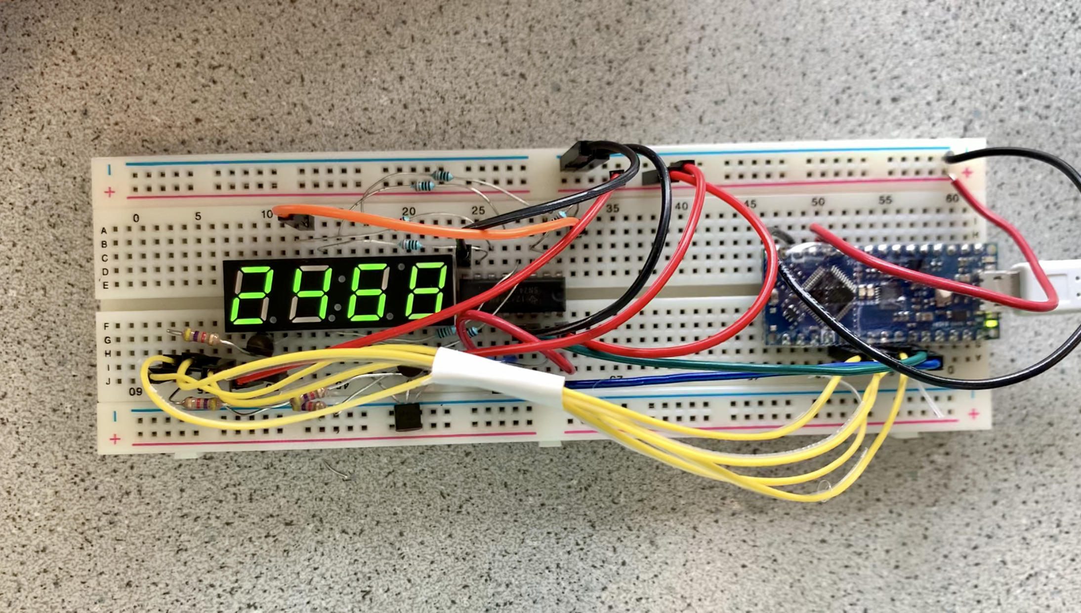
The code was edited to define which pin from the schematic went to each of D2-D7 on the Nano. Our code and circuit were error-free on the first try, which illuminated the display in bright green the number 2468, the number we specified in our code.
At the end of part 2, we added code to allow for values over 9999 to be displayed on the four-digit 7-segment display. When the number to be displayed is greater than 9999, the number is represented in scientific notation and the power of ten must be assumed to be 4.
Resources
[1] C. Poitras, Phototransistors & Display, ECE 3400, September 27, 2021.