Objective
- Build the physical robot
- Callibrate the servos
- Use ultrasonic sensors to dictate robot movement
The Body
The robot itself is composed of a metal housing, three wheels, two servos, two battery packs, a breadboard, wires, miscellaneous sensors, and an Arduino Nano.
The body of the robot was constructed by affixing a castor wheel to the front of the robot and two wheels to either side of the back of the robot. The castor wheel can spin freely while the rear wheels are each attached to the gear of a servo.
Once the three wheels were attached, the two battery packs were velcroed to the top of the robot. One battery pack consists of three AA batteries in series which will ultimately power the servos while a 9V battery will power the Arduino. The breadboard which houses the Arduino and three ultrasonic sensors (US) is affixed on top of the batteries. One US faces front, one faces right, and one faces left.
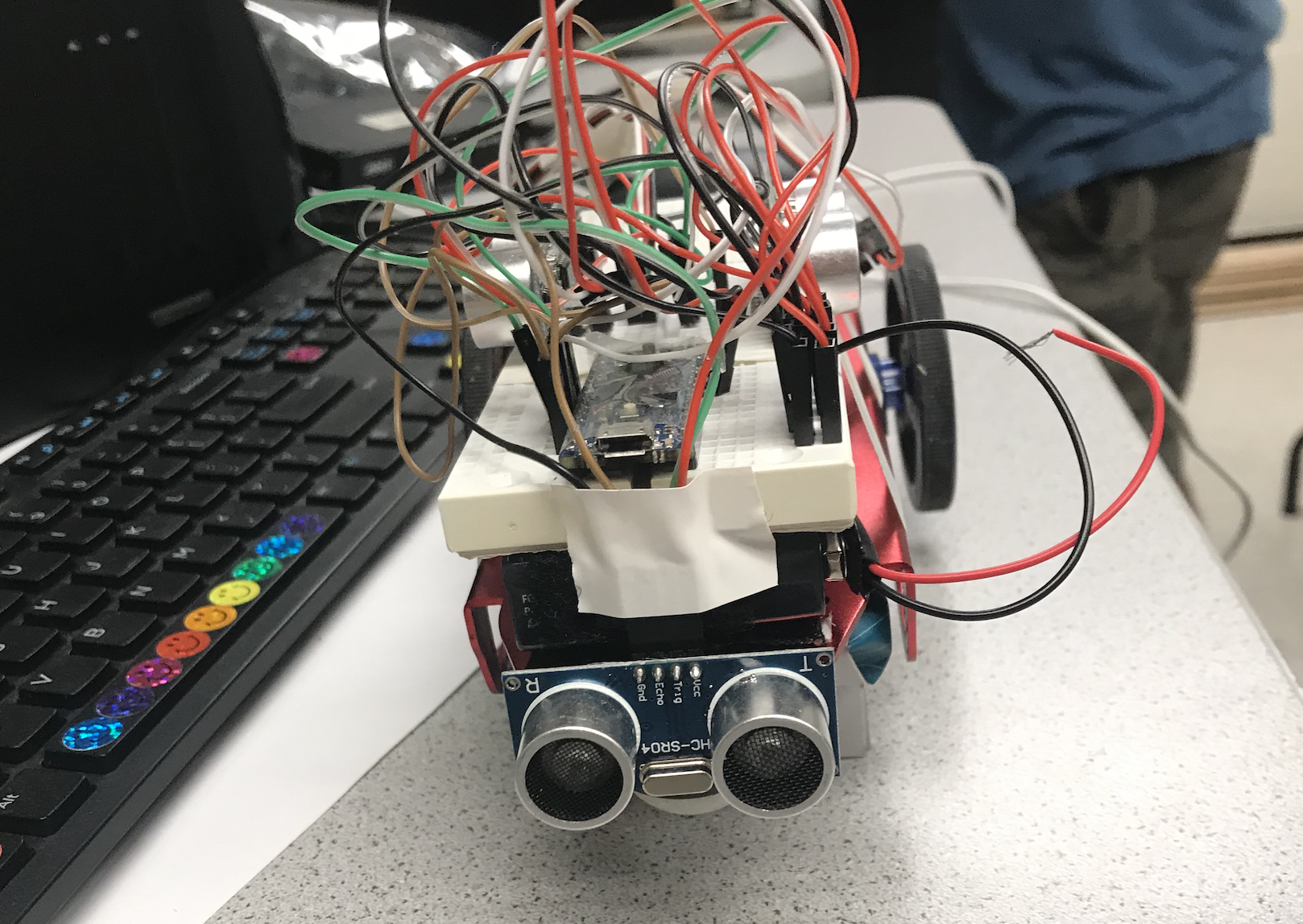
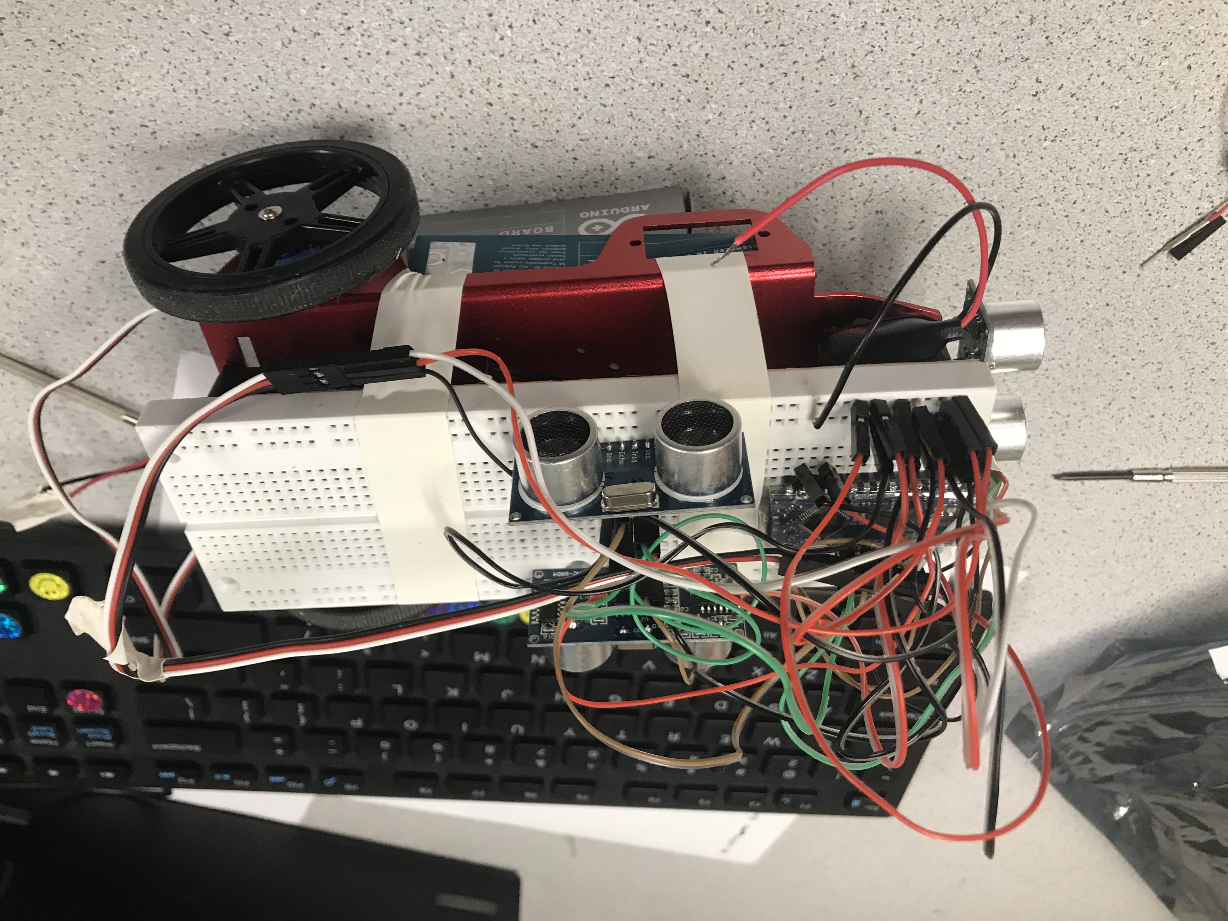 Figure 2: The Completed Robot (front view)
The Servos
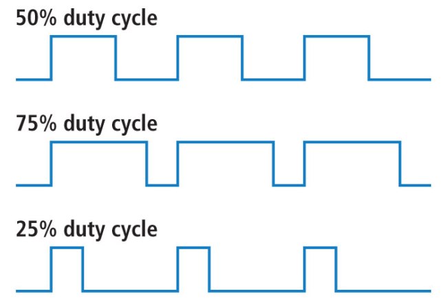
The servos each need to be connected to power, ground, their signal input to a Pulse Width Modulation output pin on the Arduino. The duty cycle of the PWM pin determines how fast and in which direction to spin the motor. At a duty cycle of 50%, or writing 90 to the servo from the Arduino Servo library should make the servo motor stop.
90 was written to both servos, then using a screwdriver the servo was calibrated by adjusting a potentiometer until the servo stopped moving.
The First Drive
To demonstrate that our servos and frame were set up and calibrated correctly, we demonstrated that the robot could move around. The goal was to get the robot to move forward, turn left, turn right, and come back to its initial position - almost like a driver’s test.
Once the servos were calibrated, the robot could predictably move around. By writing positions to the servos followed by a delay in milliseconds, it was possible to get the robot to do the turns and movements we desired.
After a little trial and error with servo positions and delay times to get sharper turns and straighter ‘forwards’, the servo was able to loop through going forward, turning around, coming back, and reorienting itself where it started.
The Ultrasonic Sensors
The ultrasonic sensors have 4 pins each: Vcc (5V), ground, trigger, and echo.
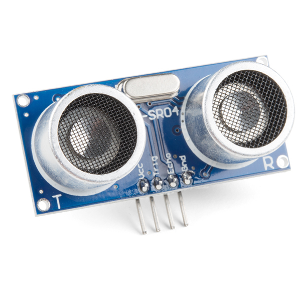
When a pulse is sent to the trigger pin of the sensor, the sensor sends out ultrasonic pulses. When those pulses bounce off of an object and come back, the sensor outputs a pulse on the echo pin. The time between when the trigger was sent and the echo was received can be used to calculate how far away the object is using the speed of sound.
The use of three US for our robot would theoretically require six digital pins from the Arduino: three triggers and three echos. However, this is too much to sacrifice because other sensors will require these digital pins in the future. One solution, which is the solution we have done, is to tie all three triggers together and have separate echos. Then, when an echo is received on a pin, an interrupt service routine is used to distinguish which echo is for each of the front, left, and right sensors. The distance from the object is then calculated and stored in centimeters.
The distances are then printed to the serial monitor in the format:
Left Sensor (cm) :: Front Sensor (cm) :: Right Sensor (cm)
As to not overflow the serial monitor with too many numbers, we print only every fourth set of distances. An example serial monitor snippet when all three sensors are connected and the robot is moving forward reads:
20.2 :: 14.3 :: 10.1
20.3 :: 12.9 :: 10.0
20.1 :: 10.5 :: 10.2
The distance to the front sensor is steadily decreasing while the distance to the left and the right remains generally constant.
The Maze
Using the three US sensors, the goal was to accurately navigate the below maze:
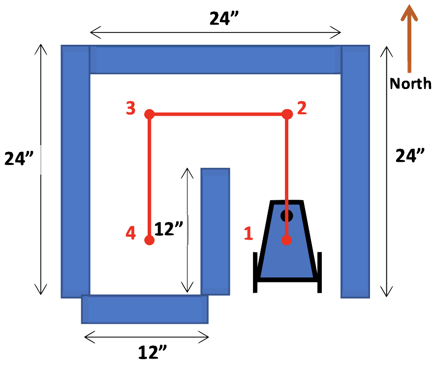
The robot was able to navigate the entire maze without user input. By using a switch statement with a set of cases signifying states, the maze can be navigated over and over again. The robot begins by maintaining a constant distance from the right wall. This is known as the right wall follow state. When its front sensor reads a value that is too small, it switches into the turn left state and turns left 90º. In order to completely navigate the maze, we require six unique states:
- Right wall follow (go straight and follow the right wall)
- Left wall follow (go straight and follow the left wall)
- Turn left 90º
- Turn right 90º
- Turn right 180º
- Turn left 540º (upon exiting the maze)
All the while, the robot prints to the serial monitor what it is doing and where (point 1, 2, 3, or 4 in Figure 4) it is. For example, after reaching point 4, the serial monitor would begin to read:
Stopped at Position 4 facing South, 15.2 :: 8.0 :: 10.0
Turning Around
Moving to Position 3
...
The Final Demo (Video)
After setting up the maze and flashing the code, we set down our robot at Position 1 and hit record. The robot successfully navigated the maze with no assistance and then came back to its starting point, ready to run again.
Resources
[1] Duty Cycles, https://cdn.sparkfun.com/assets/f/9/c/8/a/512e869bce395fbc64000002.JPG, accessed Sept 26, 2021.
[2] Ultrasonic Distance Sensor, from https://cdn.sparkfun.com//assets/parts/1/3/5/0/815569-Ultrasonic_Distance_Sensor_-_HC-SR04-01a.jpg, accessed Sept 26, 2021.
[3] C. Poitras, Intro to the Arduino, Servos, and Sensors, ECE 3400, September 7, 2021.